Road Embankment Construction
Roads placed over subsoil with low bearing capacity or with high settlement characteristics often settle to an unacceptable extent due to consolidation of the subsoil. These settlements are due to the weight of the road embankment imposing a load on the subsoil which it cannot sustain. If the road embankment is constructed out of expanded polystyrene (EPS) geofoam the load on the subsoil is much reduced and the settlement is reduced or eliminated. GeoSpec® lightweight fill is the trademark used to identify Plasti-Fab EPS geofoam used in road embankment applications.
Often poor soil conditions exist at rivers, muskegs or bogs where a bridge structure is supported on a firm foundation either directly or by piles. The road embankment is typically constructed at increased depth due to the ground profile which emphasizes the likelihood of soil settlement when poor soil conditions exist. Soils that have low bearing capacity or large settlement characteristics are soft clays with a high content of fines and water, non-cohesive soils (gravel, sand) with a high content of organic material and water, or any soil with a high content of organic material (peat is the worst example). With sufficient depth of these types of subsoil, settlement can continue indefinitely. Adding additional fill to a road embankment that has settled to bring it back up to original grade increases the load on the subsoil and the settlement continue.
Material property requirements for GeoSpec lightweight fill material are different from requirements for thermal insulation applications. A key material property for design is compressive resistance. The compressive resistance at 1% strain as provided in Plasti-Fab Product Information Bulletin 1002 is within the elastic limit of EPS geofoam and is accepted as the compressive resistance to limit long-term deformation under structural load such as in embankment fill applications.
Since GeoSpec fill material density is low relative to standard aggregate backfill materials, vertical stresses that develop behind a bridge abutment walls are much lower than for an aggregate backfill. Lateral forces exerted by GeoSpec fill material are minimal because the Poisson's ratio of GeoSpec fill material within its elastic stress range is close to zero and, therefore, is significantly less than the Poisson’s ratio for soil.
The light weight of GeoSpec fill material results in reduced vertical stresses. As well, the tendency of the interlocked GeoSpec fill material to settle as a block with a slight tilt away from the wall face reduces potential lateral load on a wall.
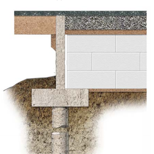
The low mass and relatively high compressibility of GeoSpec fill material may also offer an additional advantage by limiting horizontal forces against retaining structures. The transition zone between the GeoSpec fill material and soil should be free draining. Adequate subsoil drainage must be provided to prevent development of hydrostatic pressure and buoyancy. Horizontal forces on bridge abutments can be reduced or completely eliminated by leaving a small space between the embankment fill and the bridge abutment. Where horizontal forces are eliminated on bridge abutments a lighter more economical design is possible.
The design is established to provide a lightweight embankment that will carry the required highway load without overloading the subsoil and so cause settlement of the pavement structure above. A design can be established over a wide range of GeoSpec lightweight fill types providing compressive resistance which varies based upon expected compressive load. Design considerations that will also influence the GeoSpec lightweight fill material type used include the use of a concrete slab over the lightweight fill to distribute loads, the depth of gravel above the lightweight fill, pavement design and the expected traffic load over the road. At the same time the total load of the embankment fill must be kept below the level of load on the soft subgrade that would produce unacceptable settlement.
There are now numerous technical papers published to provide design assistance for the use of EPS geofoam in road construction. For example, in 2004 the National Cooperative Highway Research Program published NCHRP Report 529. This document provides design guidelines for EPS geofoam used in highway road embankment applications.
Several publications from ASTM International provide additional information on basic considerations for the use of expanded polystyrene (EPS) geofoam in geotechnical projects and guidance on quality assurance for EPS Geofoam blocks.
Where blocks are placed on sloping terrain or where high fills are used, consideration should be given to anchoring the GeoSpec fill blocks. The table below provides some examples of published values for coefficient of interface friction between EPS geofoam and other materials.
| Interface | Peak Factor | Residual Factor |
|---|---|---|
| Foam-Foam, 20kg/m3 (dry) | 0.85 | 0.70 |
| Foam-Foam, 30kg/m3 (dry) | 0.85 | 0.65 |
| Foam-Cast in Place Concrete | 2.36 | 1.00 |
| Foam-Textured HDPE Membrane | 1.00 | ~1.00 |
| Foam-Smooth HDPE Membrane | 0.29 | 0.23 |
| Foam-Smooth PVC Membrane | 0.70 | 0.40 |
If the calculated resistance forces along the normally horizontal surfaces between layers of GeoSpec fill material blocks are insufficient to resist horizontal driving or imposed forces, additional resistance between blocks is required to supplement the interface friction. When needed, Plasti-Fab recommends the use of barbed gripper plates at the rate of two fasteners per geofoam block in order to prevent movement during the construction process.
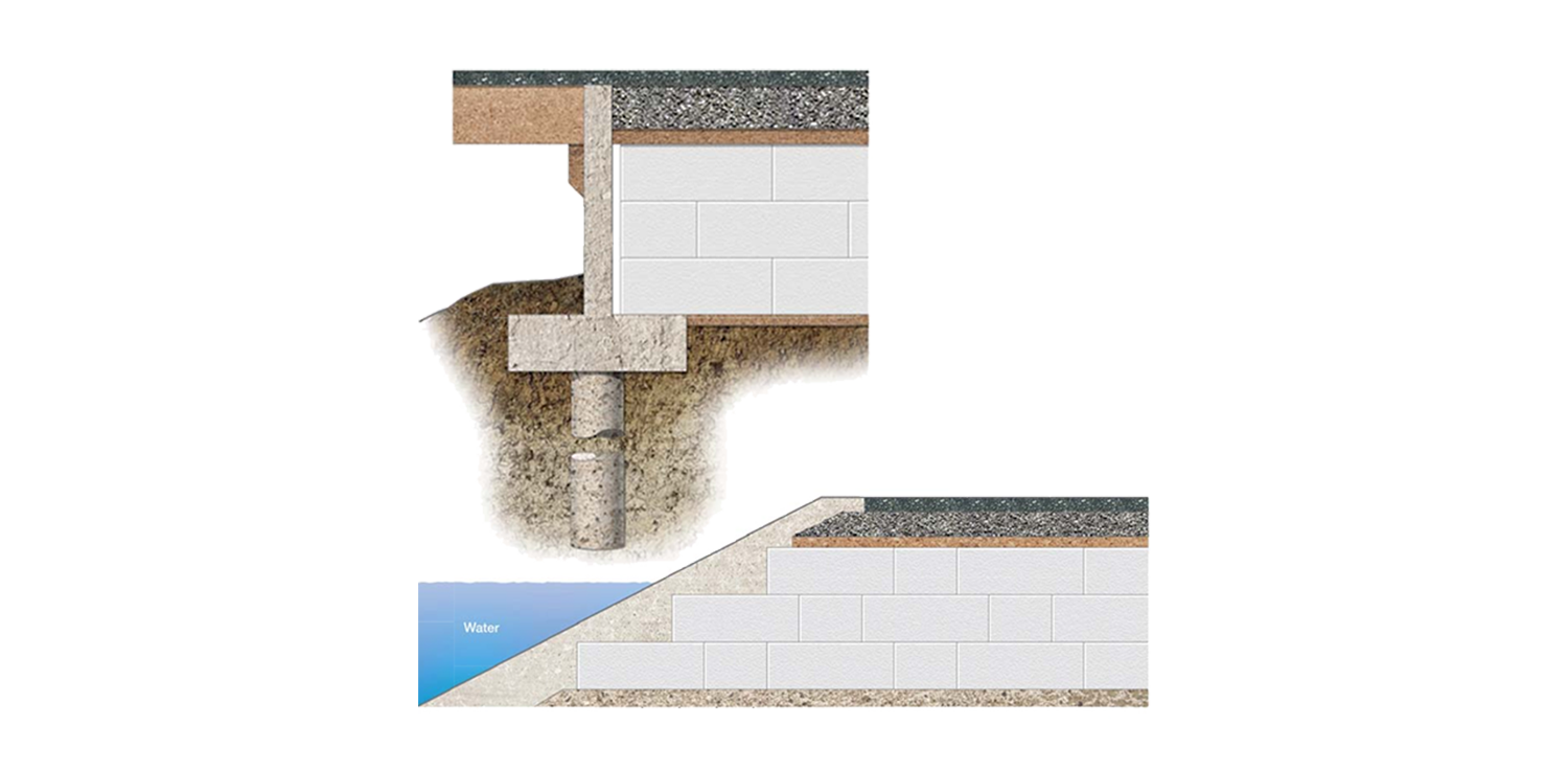
Where possible, road embankment designs should provide positive drainage to the bottom of the embankment. Where there is a possibility of trapped water on one side of the embankment drainage must be provided through the embankment.

Typically, the embankment is sloped outward to the bottom as illustrated. Where drainage may not be adequate, consideration must be given to the buoyancy force lifting the unrestrained corner of the embankment. When buoyancy force is calculated use the actual density of the block – e.g. 22 kg/m3 (1.35 pcf).
Building an embankment with vertical sides is one way to minimize any buoyancy design problems. The greatest problem of flooding and buoyancy may be during the construction phase when drainage facilities are not complete and when the pavement has not been installed to ballast the GeoSpec lightweight fill material.
The side slope of a polystyrene embankment till should not be steeper than 2:1. The blocks are usually cut with vertical sides and the soil cover establishes the slope. It is suggested that vibratory compaction equipment not be used within 508 mm (20 inches) vertically from the top surface of blocks. It has been found that plate vibratory has been the most suitable for compaction of unbound material in the pavement system.
For additional information on EPS geofoam construction principles see Plasti-Fab Product Information Bulletin No. 1002.
PIB 1003 - GeoSpec Lightweight Fill Material for Road Embankment Construction
PIB 1002 - GeoSpec Lightweight Fill Material Construction Principles